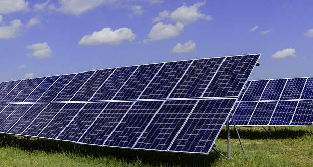
In recent years, environmental protection has become an issue of great concern. Jinshan and Yinshan are not as green as green water and green mountains. The photovoltaic industry has also developed rapidly recently. Of course, there will be many problems, even fire in serious cases. According to a foreign investigation report, the cross use of MC4 connectors by different manufacturers and non-standard installation of photovoltaic connectors are important reasons for causing fires. Regarding the issue of cross use of MC4 connectors, please refer to another article we wrote titled "Precautions for MC4 Connector Solar Waterproof Plug". Today, we will mainly introduce how to correctly install MC4 photovoltaic connectors.
1. Some problems appearing on the market
In photovoltaic power generation systems, MC4 photovoltaic connectors mainly serve as connections between inverters, components, combiner boxes, and other components. If installed in the factory, due to the complete process, it is generally reliable. However, about 10% of MC4 photovoltaic connectors need to be installed on site, which can easily lead to non-standard crimping due to a lack of training and the use of professional tools during on-site installation.
2. Types of MC4 connector metal cores and their advantages and disadvantages
Everyone knows that the metal part is the main flow part of the connector. Currently, most MC4 solar connectors on the market use "U" shaped terminals, also known as stamped metal cores, because their production process is made of copper sheets. Of course, due to this molding method, the benefits are greatly improved production efficiency, reduced costs, and can be arranged on a chain, In this way, automated machines can be used for stamping during large-scale production in the factory, ensuring quality.
In addition to the "U" type terminal, there is also an "O" type terminal, which is also known as a machined metal core because its manufacturing process is made by drilling holes at both ends of a copper rod. Due to the fact that the "O" type terminal is made by single cutting, it can only be crimped individually and is not suitable for stamping with automated machines.
3. Principle of crimping
The firmness of crimping mainly depends on the use of tools and operating specifications.
The principle is that as the height decreases, the "U" shaped part is compressed and bent, and finally tightly wraps around the copper wire on the wire. The height is very important, and special attention should be paid when making stamping dies. Of course, we cannot crimp too tightly just because we want to be firm, because being too tight can damage the copper wire structure, reduce the pulling force, and may also reduce the conductivity. So remember to check after we finish stamping.
4. Evaluation rules for crimping quality
① The height and width of crimping shall meet the requirements and can be measured with Vernier scale.
② The pulling force meets the requirements. For example, 4mm ² The wire must have a minimum pulling force of 310N. For details, please refer to IEC 60352-2 "Solderless Electrical Connections"
③ Power on performance. Such as resistance, resistance stability, etc
④ Appearance. Such as cracking, burrs, etc


